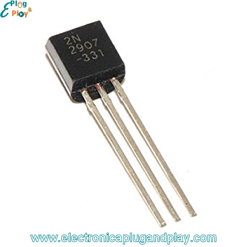

When the lettering of this transistor is facing you, the pins from left to right are: emitter, base and collector. And in this case, the “device” to switch on will be the PNP transistor (see below).įor this circuit the PNP transistor is a 2N4126 (it is what I had on hand). Usually, the device you want to switch on is between the positive voltage (e.g., battery) and the collector pin. It is this larger current being permitted to flow from collector to emitter that allows a device to be turned on, that’s how NPN transistors work like a switch. This allows a small current to flow into the base pin, which means a larger current can flow from the collector to the emitter pin. Then to switch it on (see Fritzing diagram), the voltage on the base pin must be higher than the voltage on the emitter pin. This large resistor connected to zero volts (ground) ensures that any interference in the air cannot accidentally turn it on, but has high enough resistance that a larger voltage (through a smaller resistor) can still turn it on. With an NPN transistor, the base pin is kept at a low voltage via a 10 kOhm pull down resistor to keep it switch off. In this circuit the NPN transistor I used is a 2N2222A, which, when the lettering if facing you has the pinout from left to right: emitter, base and collector. You will need to look up which pin is which for the specific BJT you are using, but in the photo of the BJTs I have labelled the ones I am using. They each have three leads, called: base, collector and emitter. In this circuit the BJTs are being used as a switch.

Bipolar transistor project how to#
There are many descriptions on the internet of what BJTs are made out of, and how to use them (this Youtube video from Applied Science is very useful) so I will only give an overview of these transistors to give an understanding of the circuit.
Bipolar transistor project code#
I will include some Arduino code below if you want to try it. This Instructable is focused on the BJT circuit to keep it simple, but ultimately will use a microcontroller to latch it. Therefore, in this Instructable I will show my prototype push-button on/off circuit with two BJT transistors, which is reminiscent of the MOSFET circuit. In a previous project I made a push-button on/off circuit using MOSFETs, which would work but MOSFETs are overkill. (If you are curious, my plan is to use two AAA batteries and add an inexpensive boost converter to boost the voltage to 3.3 volts which is rated voltage of the BME280.) I will add the option for a subsequent press of the button to turn off the device to further save power. The device will be used by people who are not so familiar with the device, so the operation should be simple, and I want it to turn off automatically after one minute to save power (they forget to turn things off). That project will be battery-operated and use an Atmega328 microcontroller, a BME280 environmental sensor and a liquid crystal display (LCD) to show the results. I have need of a ON/OFF circuit for a future project.


 0 kommentar(er)
